RK-2026-0498
| Project | Structural inspection report |
| Client | Weir Street Developments Ltd |
| Site | Former mill warehouse, Weir Street, Calder Vale |
| Report type | Defect investigation |
| Reference | RK-2026-0498 |
| Issue | 1 |
| Date | 22 Apr 2026 |
Sample report
| Structural inspection report | RK-2026-0498 |
Issue record and quality management
Status code: S4
| Revision | Date | Status | Description | Author | Checked | Approved |
|---|---|---|---|---|---|---|
| P01 | 27 Apr 2026 | Draft | Draft for internal check | IS | RA | |
| A | 30 Apr 2026 | Issued | First issue to client | IS | RA | RA |
Distribution
| Name | Organisation | Copies |
|---|---|---|
| Weir Street Developments Ltd | Weir Street Developments Ltd | 1 |
Prepared, checked and authorised in accordance with the quality management procedures of Report Kit 360.
Prepared by Imogen Stather Report Kit 360 Date: 30 Apr 2026 | Checked by Rhys Antrobus Report Kit 360 Date: 30 Apr 2026 | Approved by Rhys Antrobus Report Kit 360 Date: 30 Apr 2026 |
Limitations. This report is limited to the elements of structure described. Building services, timber decay, damp penetration, contamination and asbestos are specialist matters and are outside its scope unless expressly stated. Hidden or inaccessible parts of the structure were not inspected and cannot be guaranteed free from defect.
This report is confidential to Weir Street Developments Ltd and is provided for the purpose described in the introduction. Report Kit 360 accepts no responsibility to any third party who relies on it, in whole or in part, without our prior written agreement. Where our report refers to information supplied by others we have assumed it to be accurate unless stated otherwise.
| Structural inspection report | RK-2026-0498 |
| Structural inspection report | RK-2026-0498 |
Executive summary
Weir Street Developments Ltd asked us to inspect cracking in the north wall of the former mill warehouse before its conversion to apartments. The three-storey building (about 1885) is of solid brick load-bearing walls with timber floors on cast-iron columns. A stepped crack up to 6 mm wide (BRE category 3) runs from the ground-floor window at grid C to the parapet, with finer diagonal cracks at grid D. The pattern, the taper (wider at the top) and the position over the culverted mill race indicate differential settlement of the north wall at its western end, probably long-standing but recently reactivated by leakage from the culvert. The wall is stable at present. We recommend a six-month programme of crack monitoring, a CCTV survey of the culvert, trial pits to confirm the foundation, and, depending on the results, local underpinning and stitching of the cracks before conversion.
| Structural inspection report | RK-2026-0498 |
1 Introduction
Commission
| Client and instruction | Weir Street Developments Ltd; email instruction 2 April 2026 | Purpose of the inspection | Investigate the cause and significance of cracking in the north wall before conversion |
|---|---|---|---|
| Inspection method | Visual inspection from ground level, cherry picker and internally; crack widths by comparator; levels by digital level | Exclusions | Foundations (not exposed); roof structure (viewed from the top floor only) |
| Date(s) of inspection | 22 Apr 2026 | Attendees | The author; the client's facilities manager |
| Access limitations | Roof accessed by ladder to the eaves only; plant room locked | Documents and drawings reviewed | 2021 condition report; architect's survey drawings WSD-A-001 to 004 |
The warehouse was built around 1885 for the adjoining cotton mill and used for storage until 2019. A previous condition report (2021) noted hairline cracking at grid C. The client's architect reported that the crack had widened during the winter of 2025 to 2026, which prompted this inspection.
| Structural inspection report | RK-2026-0498 |
2 Form of structure
Structure
| Orientation convention used in this report | Elevations named by compass point; grid A to F west to east, 1 to 4 south to north | Number of storeys | Three |
|---|---|---|---|
| Structural frame | Load-bearing solid brick walls with internal cast-iron columns | Floors | Timber joists on timber beams and cast-iron columns |
| Roof structure | Timber queen-post trusses, slate covering | Cladding / external walls | Solid brick, 450 to 560 mm |
| Foundations (known or assumed) | Unknown; assumed brick footings on clay | Load path | Roof and floors to external walls and columns, to footings |
| Movement joints | None | Date of construction (approximate) | About 1885 |
Loads from the timber floors are carried by cast-iron columns on a 3.6 m grid and by the external walls, which are 450 mm to 560 mm solid brick. The roof is a timber queen-post structure spanning between the north and south walls. Foundations are unknown; brick footings on clay are assumed. There are no movement joints. The mill race passes beneath the north-west corner in a brick culvert.
Figure 2.1 — North elevation with the inspection area and photograph locations
| Structural inspection report | RK-2026-0498 |
3 Inspection area
3.1 North elevation and ground floor
1. The north elevation was inspected from ground level and from a cherry picker; the internal face was inspected at ground and first floor. 2. Crack C1 runs in a stepped pattern through the bed and perpend joints from the sill of window N3 to the parapet, 6 mm wide at the top tapering to 2 mm at the sill; the brickwork is fractured through in places. 3. Crack C2 is a diagonal crack 2 mm wide above window N4 at grid D, following the line of an old arch repair. 4. Cracks C3 and C4 are hairline cracks in the internal plaster at first floor directly behind C1. 5. The parapet coping is displaced 10 mm at grid C and the wall tie exposed there is heavily corroded. 6. The timber floor bearings at grid B/2 and C/2 are sound; no distortion of the floor was measured. 7. Surface water from the yard discharges towards the culvert inlet, which is partly blocked.
North elevation showing the stepped crack at grid C | Crack C1 with tell-tale installed |
Diagonal cracking above the ground-floor window, grid D | Corroded wall tie exposed at the parapet |
| Structural inspection report | RK-2026-0498 |
4 Defect register
| Structural inspection report | RK-2026-0498 |
| Ref | Element | Location | Condition / description | Cause | Rating | Photo | Measurement | Recommended action | Timescale |
|---|---|---|---|---|---|---|---|---|---|
| 6 | Timber floor bearings | Grids B/2 and C/2 | Sound; no distortion. | 0 | None | ||||
| 4 | Internal plaster | First floor behind C1 | Hairline cracks C3 and C4. | As C1 | 1 | 0.3 mm | Make good after stitching | Before conversion | |
| 2 | North wall | Grid D, above window N4 | Diagonal crack C2, 2 mm. | Settlement; old arch repair | 2 | 2 mm | Monitor; stitch with C1 | 6 months | |
| 1 | North wall | Grid C, window N3 to parapet | Stepped crack C1, 2 mm to 6 mm, tapering wider at the top. | Differential settlement over the culvert | 3 | 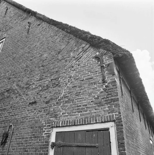 | 6 mm | Monitor; trial pits; underpin and stitch | 1 to 6 months |
| 5 | Culvert inlet | Yard, north-west corner | Partly blocked; overflowing in rain. | Debris | 3 | 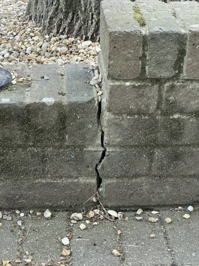 | CCTV survey and clear | 1 month | |
| 3 | Parapet | Grid C | Coping displaced 10 mm; wall tie corroded through. | Movement; corrosion | 4 | 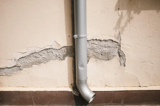 | 10 mm | Fence off; remove loose coping; replace ties | Immediate |
Table 4.1 — Crack classification (BRE Digest 251 bands)
| Ref | Element | Location | Crack width (mm) | BRE 251 category | Class | Orientation | Taper | Monitoring |
|---|---|---|---|---|---|---|---|---|
| C1 | North wall | Grid C, N3 to parapet | 6.00 | 2 | Aesthetic | Stepped, diagonal | Wider at top | Yes, TT1 |
| C2 | North wall | Grid D, above N4 | 2.00 | 1 | Aesthetic | Diagonal | Uniform | Yes, TT2 |
| C3 | Internal plaster | First floor, grid C | 0.30 | 1 | Serviceability | Diagonal | Uniform | No |
| C4 | Internal plaster | First floor, grid C/D | 0.20 | 3 | Aesthetic | Vertical | Uniform | No |
| C5 | Parapet | Grid C coping joint | 10.00 | 1 | #REF! | Horizontal | Uniform | Yes, TT3 |
| C6 | South wall | Grid E, ground floor | 0.50 | #REF! | #REF! | Vertical | Uniform | No |
| Highest damage category recorded | #REF! |
| Widest crack recorded | 10.00 mm |
4.1.1 Monitoring
Table 4.2 — Crack monitoring record
| Tell-tale / stud ref | Location | Installed | Baseline (mm) | Reading 1 (date / mm) | Reading 2 (date / mm) | Net change (mm) |
|---|---|---|---|---|---|---|
| TT1 | C1 at parapet | 2026-04-22 | 6 | |||
| TT2 | C2 above N4 | 2026-04-22 | 2 | |||
| TT3 | Parapet joint, grid C | 2026-04-22 | 10 |
| Structural inspection report | RK-2026-0498 |
5 Discussion
The crack pattern (stepped, tapering, wider at the top, located over the culvert) is characteristic of differential settlement at the north-west corner rather than thermal movement or lintel failure. The reactivation in winter is consistent with softening of the clay by leakage from the culvert, which is partly blocked and overflowing at the inlet. Category 3 damage is serviceability rather than stability, but continued movement could affect the stability of the parapet and the window heads. Corrosion of the wall ties at the parapet is a separate, age-related defect.
| Structural inspection report | RK-2026-0498 |
6 Recommendations
Immediate: fence off the pavement below the parapet at grid C and remove the loose coping. Within one month: CCTV survey of the culvert and clear the inlet; install three tell-tales and take monthly readings for six months. Within three months: two trial pits at grid C to confirm the foundation and soil. Before conversion: subject to monitoring, local underpinning at grids B to D (about 9 m), helical-bar stitching of cracks C1 and C2, replacement of the parapet ties and repointing. A structural engineer should review the monitoring results before the conversion design is finalised.
Table 6.1 — Schedule of recommendations
| Ref | Further investigation / action | Why | When | By whom |
|---|---|---|---|---|
| R1 | Fence off the pavement and remove the loose coping | Falling masonry risk | Immediate | Client |
| Structural inspection report | RK-2026-0498 |
Appendix A — Photographs
Internal face of the north wall, ground floor | Timber floor bearing at grid B/2 |
North elevation showing the stepped crack at grid C | Crack C1 with tell-tale installed |
| Structural inspection report | RK-2026-0498 |
Appendix B — Calculations
Bearing pressure check on the north wall footing: characteristic loads from the roof, two timber floors and the wall self-weight to BS EN 1991-1-1, assumed 900 mm wide brick footing, presumed bearing resistance of 100 kN/m² for firm clay.
Table B.1 — Calculation table (units in the unit column)
| Item | Symbol | Value | Unit | Source / note |
|---|---|---|---|---|
| Roof load to north wall | g_roof | 6.200 | kN/m | Slates, timber and snow |
| Floor loads to north wall (two floors) | g_floor | 14.800 | kN/m | Dead and imposed, residential |
| Wall self-weight | g_wall | 48.600 | kN/m | 0.5 m x 10.8 m x 9 kN/m³ |
| Total line load | N | #CIRC! | kN/m | Sum of the above |
| Footing width | B | 0.900 | m | Assumed |
| Bearing pressure | q | #CIRC! | kN/m² | Compare with 100 kN/m² presumed |